I sent several information requests on this subject to international mailing-list and French-speaking mailing-list. I did not have any interesting return by members. I thus decided to write this page in order to share my experiment of the anaglyphs printing. This page is in construction, if you want to supplement it, to discuss it, do not hesitate to communicate to me your information and your own experiences.
According to the scientific spirit, not use such data or text without reference, thank you !
The anaglyph :
The anaglyph is a stereoscopic composite image which contains an image corresponding to the left eye and an image corresponding to the right eye. The anaglyph is the transport of the detph by the color. It is undoubtedly the simplest manner and most known at low cost with the detriment of fidelity of restitution of the initial colors. The anaglyph is a compromise, other restitution techniques much better exist but without the same facility of diffusion to a public of Net surfers (in 2009…). The colors used for this transport are not taken randomly. They are often complementary to obtain the white by cerebral fusion.
The couple of color more currently used is the red with the cyan (green+blue). This choice is particularly adapted for a system of coding of the colors which uses these primary colors so as to separate information well from the left eye and the right eye. I.e., system RVB of the CRT screens or flat panel displays which we have the practice to use. Or, the digital camera equipped with CCD/CMOS RVB sensors . A screen which is a source of light recreates the colors by their additive synthesis, i.e. that one starts from any light (black) and that one adds of luminous flows coloured to obtain the color wished by the addition balanced of those. There is here no difficulty for the anaglyph except a problem inherent in the known anaglyphic process under the name of coloured rivalry, where, an eye is dazzled or stereoscopic information by the two eyes - situation does not exist in truth what easily makes the object cannot be situated for the brain (here for more information). There is also the choice of a good couple of restitution monitor/glasses which is primordial to assess the quality of an anaglyph. For example, a red photosite which emits in a significant way in the green will introduce into the right image, the information of the image of left. A green photosite which emits in a significant way in the red will introduce into the left image, the information of the left image. This is a crosstalk, the brain is disturbed. The image is not regardable, it is unpleasant, there are ghosts. This symptom is really typical of bad monitor/glasses pair.
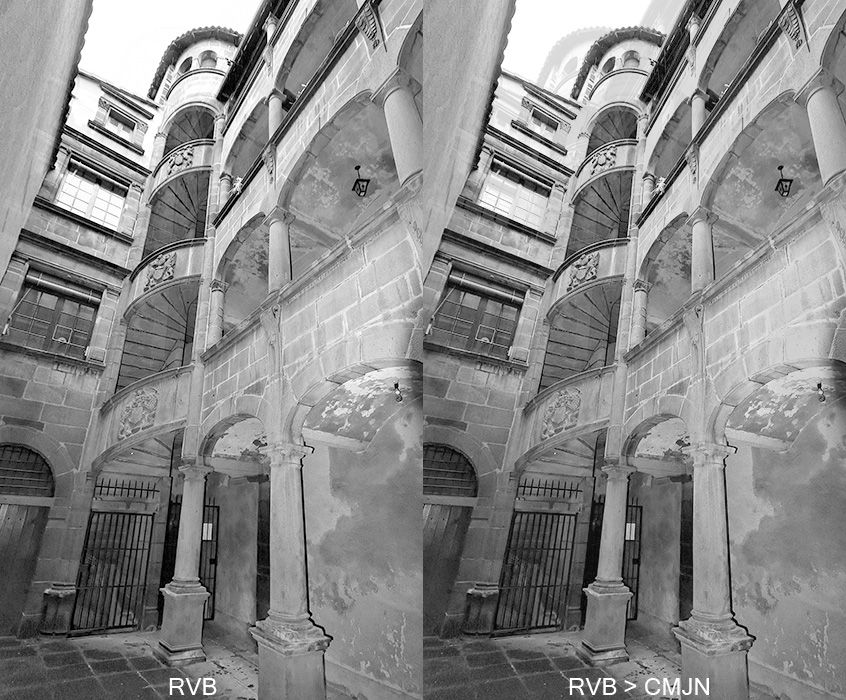
Anaglyphs printing on paper :
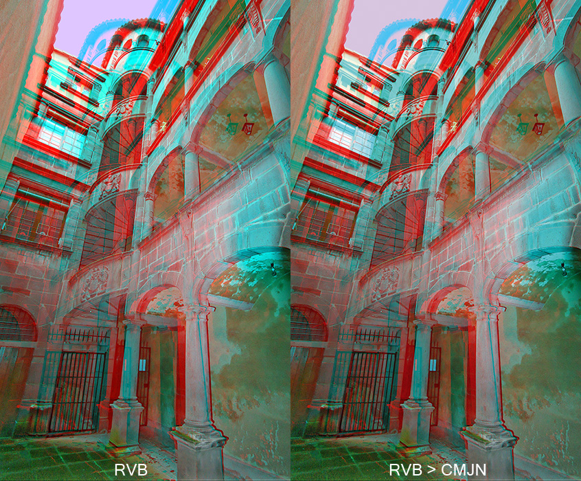
Let us come while maintaining to the problem which justifies this page, the transformation of an anaglyph who is an digital RVB image displayed in additive synthesis, by an digital image CMJN displayed by subtractive synthesis on paper !
Indeed, the diffusion/presentation of an anaglyph on the Internet is not really a problem but on the other hand it can become a true problem if one wishes to print them on paper (books, poster exhibition…). Why ? One passes from the additive synthesis of the colors to the subtractive synthesis of the colors with completely different primary colors. As the anaglyph is the transport of the depth by the color, it is necessary that this transformation is perfect, faithful and especially possible technically with the same separation quality of the red and the cyan (for red-cyan anaglyph). One must pass from RVB light sources of the screen, to the absorption spectra of the inks coloured pigments used by the printer. When one observes the images in a book, it physically occurs the opposite compared to a screen, the synthesis is subtractive. The ambient light source (whitest possible) reflect to the deposited inks on paper. These inks contain coloured pigments which absorb part of the white source of light and are reflected to enter the eye with a dominant news coloured that the white. The subtractive synthesis uses as primary color, the Cyan, the Magenta, the Yellow and the Black (to extinguish). This is the CMJN system which is used by the offset printing works or printers or the tracers. The more good transform of RVB towards CMJN will be and better quality anaglyph will be.
The problem becomes complicated a little more because each reproduction device, of share the characteristics of their basic colors, are able to display only one set of the possible colors that the eye is able to observe and to differentiate. This set of reproducible colors by the hardware is called the gamut. The gamut of RGB screens is generaly wider than that of inks CMJN. Worse still, according to the inks standard used by the printer (European Euroscale, American SWOP), the gamut is not completely the same one. And to finish, for the same ink, the gamut is different if one deposits it on art paper, coated, fine, recycled…
The fidelity of the true colors seen by the eye, acquired originally by a RGB camera with very wide gamut (like ProPhotoRGB/ROMM RGB), restored by the CMJN inks deposited on a type of paper, very often with a not cast off printing process, can become a true headache or a discouragement for the fastidious photographer. If it does not accept a intellectual compromise, this last will undoubtedly never produce anaglyphs. One can reassure the reader owing to the fact that the observer “general public” does not see the same thing that the “specialist”, except if the comparison is directly possible. I often noted it as well on stereoscopic faults or the colors fidelity in 2D. The general public attach to the instantaneous effect, the specialist focuses on the technical defects, the graphic designer on the page layout, the artist undoubtedly on the harmony set.
The transformation is illustrated below : On the left, a triangular form that display all colors reproduced by your computer screen (in RGB). On the right, this same image but converted to CMJN Euroscale inks deposited on coated paper (then reconverted in sRGB). In fact, the right coloured triangle was processed by a software calculation for CMJN conversion. Are the two triangles identicals ? Do you see the same colors exactly ? … not exactly !
This operation is carried out in your software of image editing, in the module of transformation between gamut via ICC profiles. You must think that I “am crazy” to write that it corresponds to the aspect on paper (with Euroscale ink) that you visualize on your sRGB screen (in additive synthesis) ; but by experiment, this restitution is rather similar to the aspect which one obtains with an offset printing.
The transformation has for effect “to flatten” the colors, especially for the green and the blue which appear less sharp, less saturated. Why ? Quite simply because with this primary CMJN inks, it is impossible to synthesize the exact colors (in a subtractive synthesis way) produced by the red source, the green source or the blue source used for additive RGB synthesis . One passes from a rich gamut colors to a more reduced set.
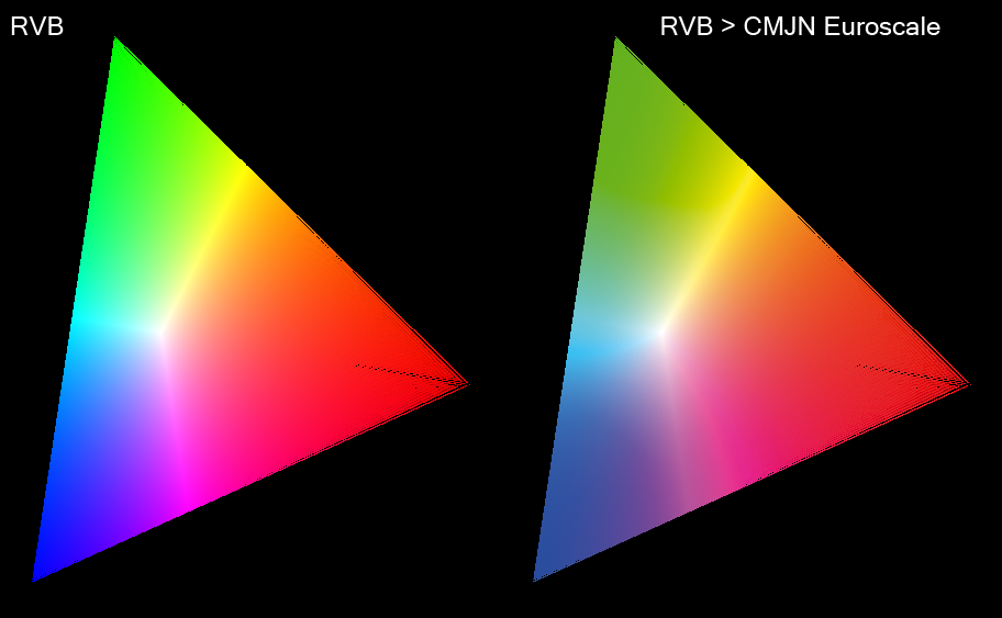
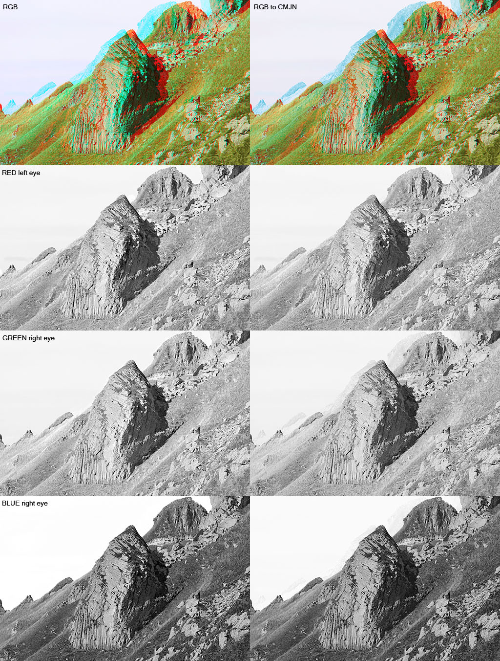
Aspect of an image RGB (gamut sRGB) after CMJN transformation ( Euroscale Coated v2 gamut).
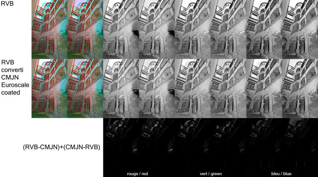
Let us examine what occurs on each RGB layer from this illustration with the image below (1st column = RGB image, 2nd column = 1st column converted into CMJN Euroscale coated v2, 3rd column = differences between RGB version and converted CMJN version - if the two coloured triangles were identical after the transformation, then the difference would be null and this third column should appear black, 2nd line = luminous flux of the red layer represented in grey level, 3rd line = luminous flux of the green layer in grey level, 4th line = luminous flux of the blue layer in grey level):
- 2nd line, on the red layer: 1st column in RGB, on the segment which joint the green vertex to the blue vertex, it does not have there red (he extinguishes). Logic since it is about the most distant place of the red vertex. The colors which are on this segment thus do not have a red light in their composition. On the right, conversion in CMJN does not have the same aspect on extinction of the red flux, CMJN conversion thus adds red to the initial colors. It is enough to observe the third column to note that there is especially more red in the greens and the cyans!!! Beurkkk !!!! for anaglyphs, one then adds the left image in the right image, one introduces crosstalk by this transformation, the image is inevitably less coherent than the initial RGB because separation between left/right channels is less good. Note that the transformation adds a also little red flux in the magentas ;
- 3rd line, on the green layer: 2nd column in CMJN, the tendency is to add green on the segment between the red and blue vertices. The quantity is stronger in blue than in the red. It is less problematic because less extremely than for the red layer. For red-cyan anaglyph , the transformation very slightly adds right image into the left image. On the other hand, one can also note that the intensity of the green is much less strong, the greens are less pure ! ;
- 4th line, on the blue layer: 2nd column in CMJN, the tendency is to add blue on the segment which joint the red and green vertices, with the total disappearance of an area of hue between the yellow and the green. Blue flux is also less strong, one obtains the blue ones less saturated. For red-cyan anaglyph, the transformation very slightly adds right image into the left image. Also note, the areas of particular forms in the 3rd right column, the places where the CMJN transformation changes much the initial colors (the green-yellows and magenta-blue).
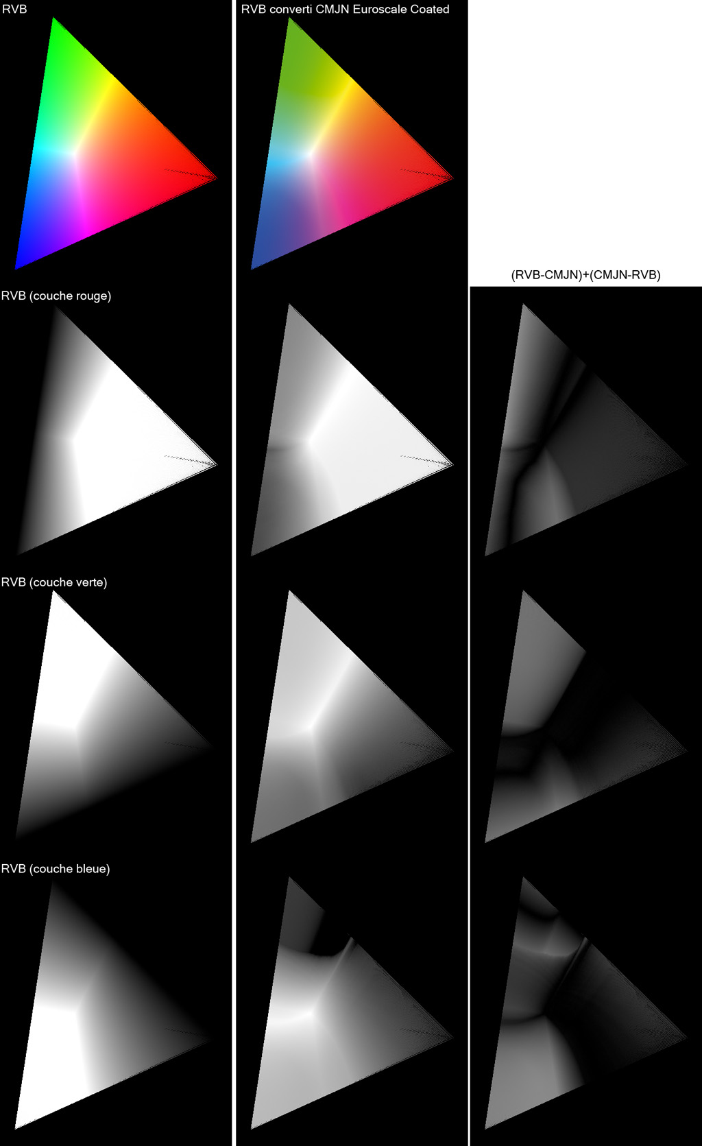
Differences in aspect of an RGB image (gamut sRGB) converted to CMJN (gamut Euroscale Coated v2), layer by layer in RGB.
Problems noted during the offset anaglyphs printing
We have just seen that the conversion of RGB towards CMJN results in a change of the initial colors and in the case of the anaglyph by the introduction of the information of an eye into the other. This transformation is thus intrinsically bad for the anaglyphic process.
The experiment that I had of the offset printing enabled me to realize that the most serious problem is the cyan ghost. I.e. when the anaglyph presents a great cyan shift in a clear area, such as for example a dark rock routed by a white sky. Or, a luminous object shifted cyan on a dark or gray bottom. I seldom noted a problem with a red ghost shift.
I developed a small software to help me to identify the risk colors and the problematic areas once printed with CMJN printer. It makes it possible to compute two colors panels. Those contain the nondiaphotic colors towards CMJN and another the diaphotic colors which will pose a problem once transformed into CMJN Euroscale. By injecting an PNG image with command line option to the software, this one creates output image where the parts which pose problems on printing CMJN Euroscale Coated (or FOGRA Coated) are highlighted in clear YELLOW.
Here 16.777.216 colors that a standard graphic computer card (8 bits DAC) can generate by the dosage of the red, green and blue with 256 digitals units RGB (red dose from 0 to 255, green dose 0 to 255, blue dose from 0 to 255) :
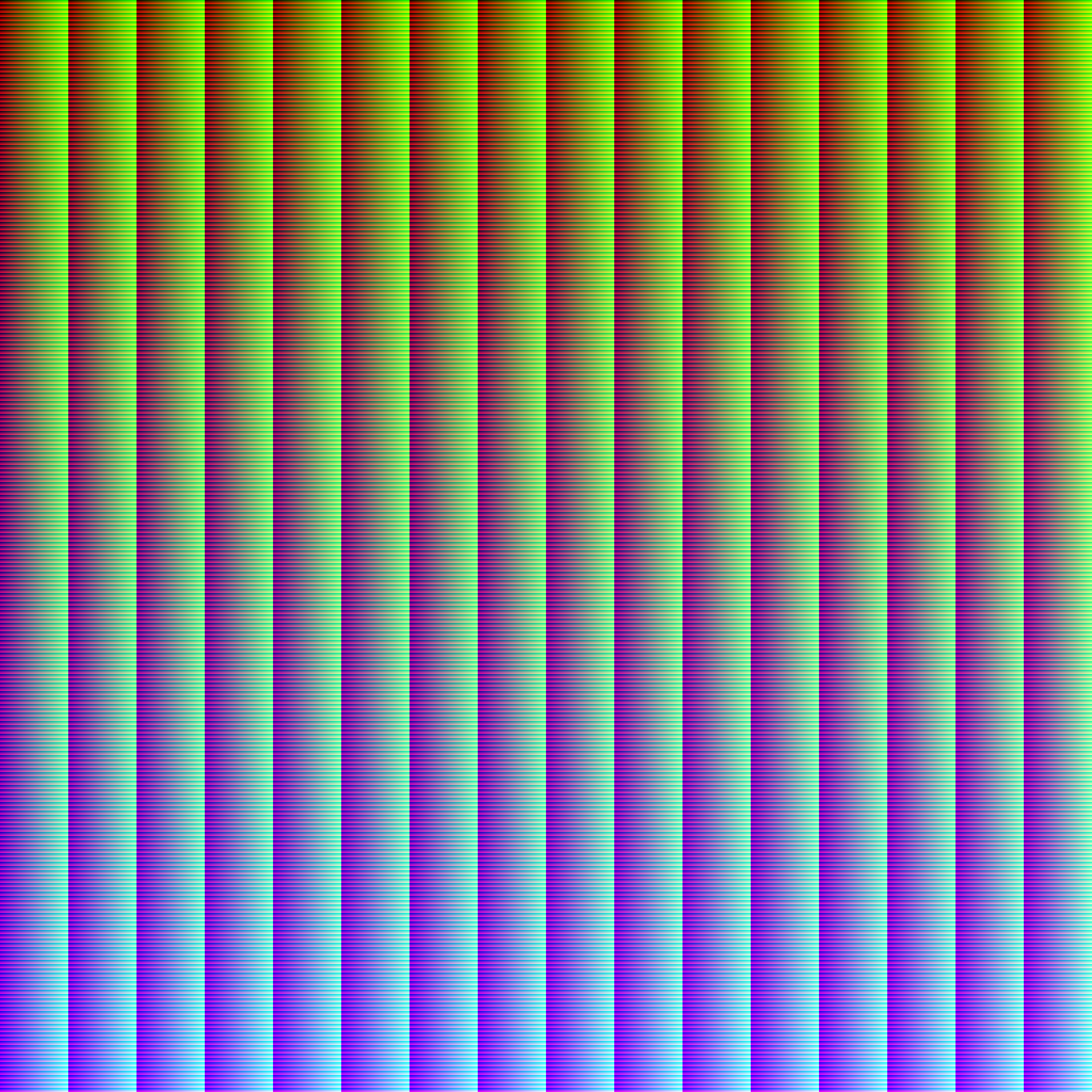
Abacus of the 16.777.216 colors that a 8 bits standard graphics card can generate by the RGB components dosage (r256*v256*b256).
CLICK ON THE IMAGE FOR HIGH RESOLUTION VERSION 4096x4096 pixels.
Here the panel of the colors which will not pose a problem for the anaglyph printing in CMJN Euroscale Coated v2. This panel is computed by my software by fixing a threshold deduced from the experiment. This threshold is a limit which I consider tolerable where the initial color is good separate image left/right eyes in RGB is not shifted too much towards the homologous eye in CMJN. The threshold is 25 DAU maximum of drift (left/right) between the initial color and the color transformed in CMJN Euroscale coasted v2 :
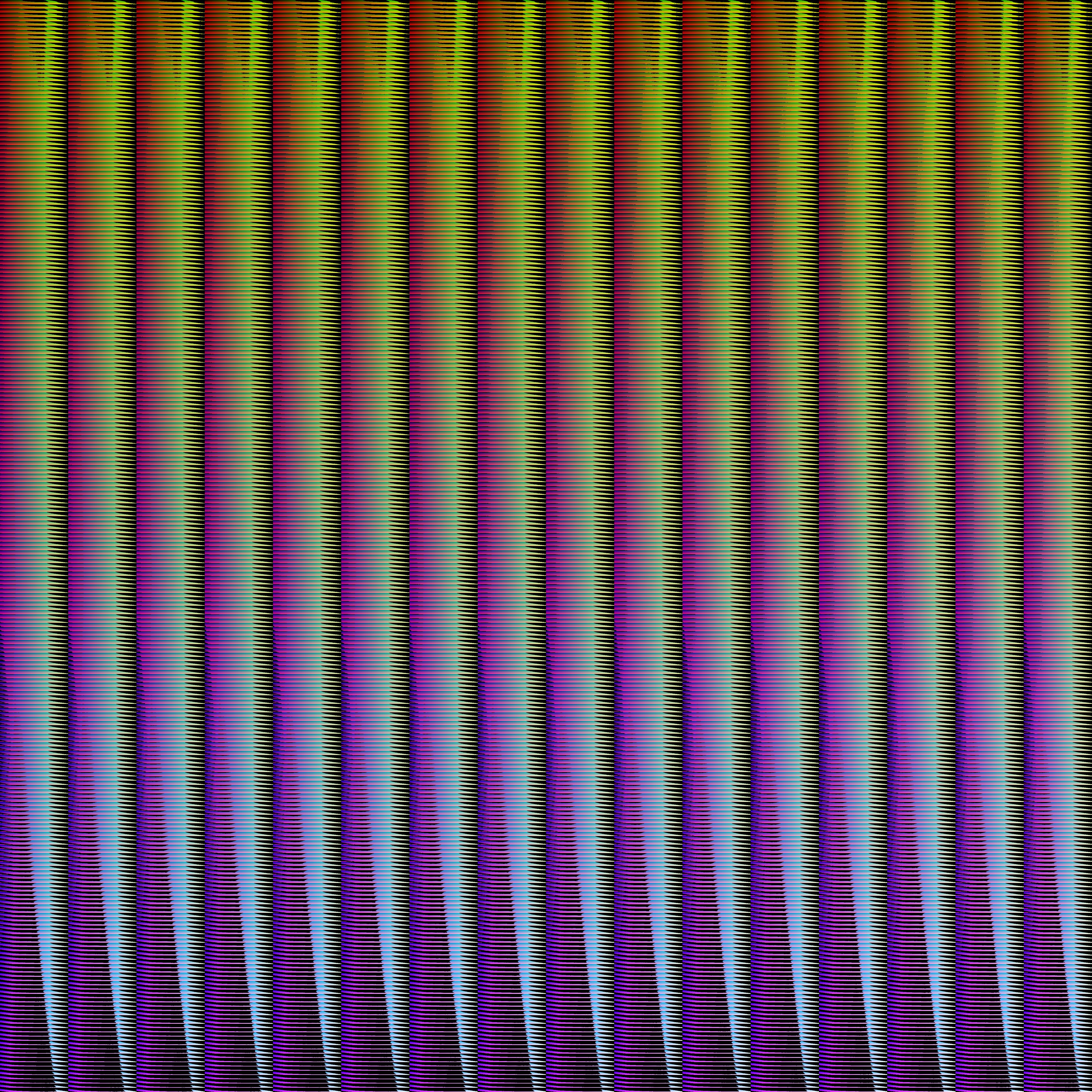
Abacus of the initial colors of an anaglyph which will not pose a problem with the CMJN printing process.
CLICK ON THE IMAGE FOR HIGH RESOLUTION 4096x4096 pixels.
Here the panel of the colors which will be a problem of the crosstalk type for the anaglyph CMJN printing in Euroscale Coated v2. I determined “in experiments” a threshold of 25 DAU maximum of drift (left/right) between the initial color and the color transformed into CMJN Euroscale coasted v2. Some colors are shifted of more than 230 DAU towards the homologous channel (left eye towards the right, or right eye towards the left) when they are transformed into CMJN. These colors are thus absolutely to avoid in an RGB anaglyph which one wishes to print in offset CMJN Euroscale inks (or FOGRA 27,39) :
Abacus of the initial colors of an anaglyph which will pose a crosstalk problem for CMJN offset printing.
CLICK ON THE IMAGE FOR HIGH-RESOLUTION 4096x4096 pixels.
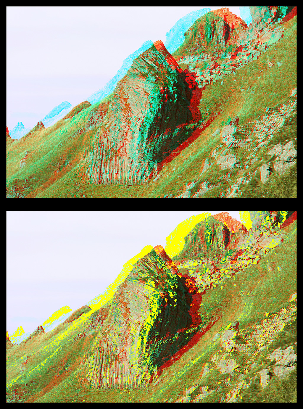
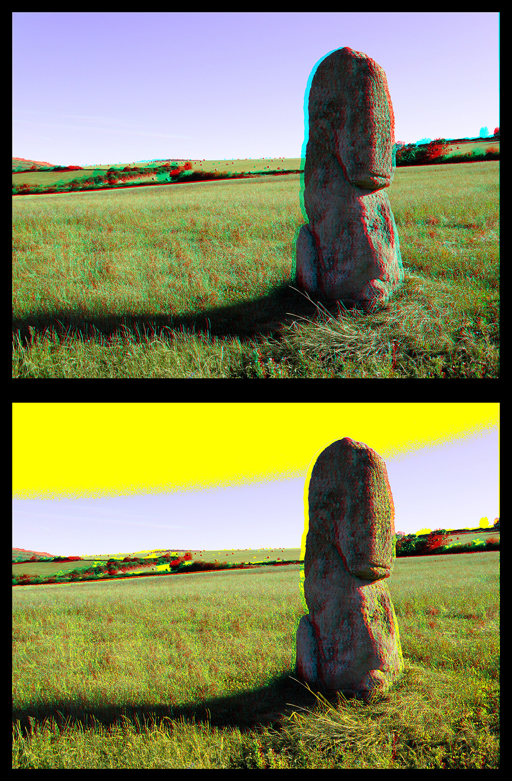
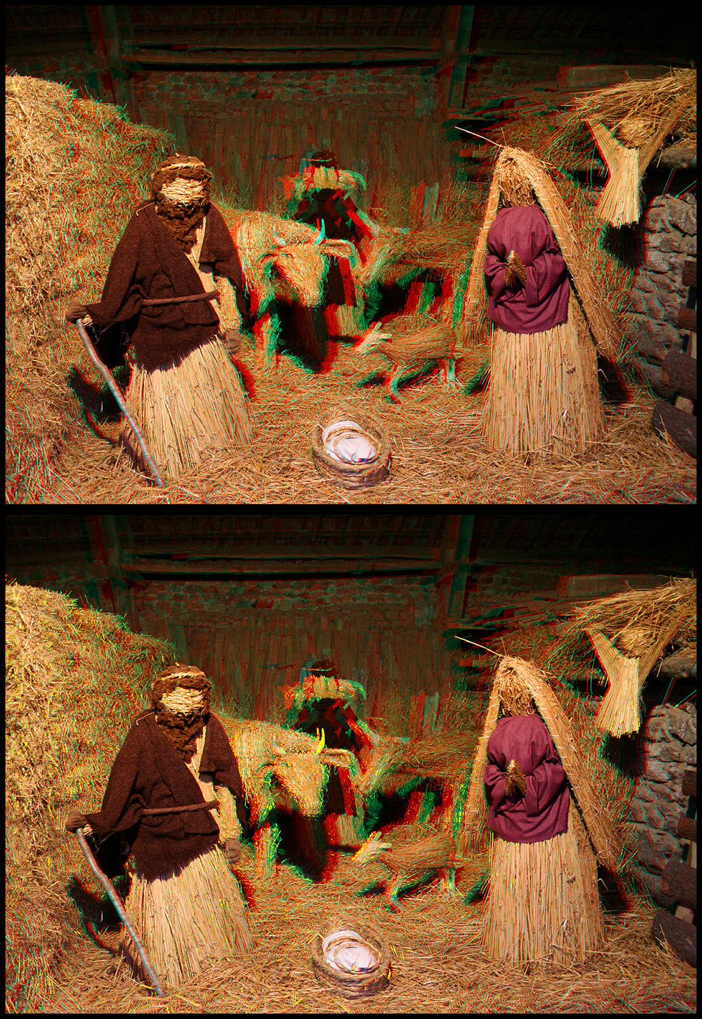
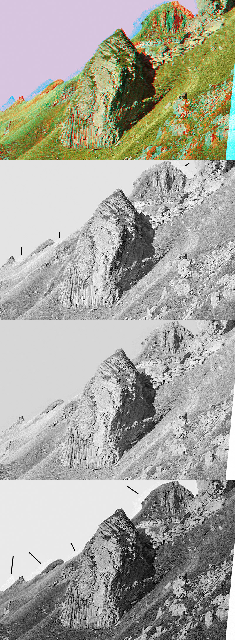
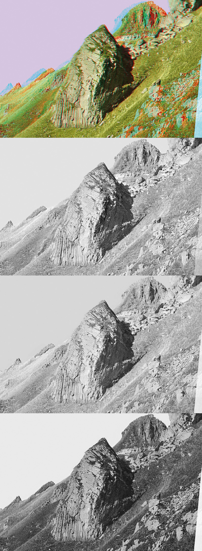
My software can analyze an RGB anaglyph. It marks in yellow the parts which will shift far too much from an eye towards the other in offset printing, parts which will make the printed anaglyph incoherent for the brain. One can also note that these crosstalk areas carried in yellow, are not inevitably perceived incoherent in the areas deprived of depth like the sky at the top of the menhir for example. There are also anaglyphs which will pass very well in offset printing because they are not contain problematics colors (like the nativity scene in straw) :
 _
_
 __
__
What to make to prepare an red-cyan anaglyph for CMJN offset printing ?
- for a purely technical reason related to the hardware of the printer, it is necessary that the images are 300 dpi resolution. Not the sorrow resample them (to add or remove the intermediate pixels). By default, the majority of the cameras are 72 dpi images. It is of course that the “dpi” have a sense only on one physical support (which has a dimension). The intrinsic quality of resolution of an image in the computer is related to the number of picture elements, many pixels ;
- Caution: appearance of a printed anaglyph is depend on the color temp of the light source which lights it. It is necessary to make your print tests with the luminous environment in which they will be probably observed (sun natural light, fluorescent tube…). A too red light will reinforce the left channel, a too blue light will reinforce the right channel ;
- most of the time, it is better to use “Dubois colors” optimization for the landscapes. The image is then more relaxing on the blue sky and the bright reds objects. The colors are balanced between the left eye and the right eye. The bad tendency of the “Dubois colors” is to shift on the green when the scene is dark, the dress mahogany tree/alezane of a quadruped, a character who becomes a Martian… The observer does not notice it with the first glance if it is about a tendency not too strong. One can improve the whole of the operation via the tuning of the color temperature in the retouching software ;
- an image with a dark bottom will have tendency to better passing than an image with a white/luminous bottom. This criterion can enter in account during the selection of the images to print ;
- it is necessary to avoid as much as possible the great red-cyan ghost : either the parallax of shooting is weak (but you decrease the effect of depth), or you arrange yourselves with the stereoscopic assembly to place volume so as to reduce the shifted areas. An window assembly will be able to often lead to strong shifts red-cyan if you have a strong parallax. One can either use the floating windows type assembly, or to carry out a stereoscopic coherence cutting . For these two last solutions, the graphic designer will be able to reproach you for leaving area red and cyan on the edges what it does not find beautiful because it does not have the practice of a stereo window. As the anaglyph is a compromise, you can also assembly it so as to reduce the shift red-cyan and deliberately to leave a window violation nonobvious and not very awkward. The general public will not see it with the first glance and the graphic designer will ask you where is the problem because he does not see it… A subtle window violation is -for me- much more bearable than a ghost with strong crosstalk. Only the “stubborn and rigid purist” will make a fixing of it. Most of the time, you do not work for him… ;
- before CMJN conversion, look at your image in the search of areas shifted cyan on white zone, or shift cyan of beige-white object on gray bottom. You will obtain doubtless a terrible incoherent ghost in CMJN. The only solution that I found is to change the color area if the image allows it. For example, to change a white sky by a blue-reddish sky which will not cause a crosstalk color. You can also try to change the tunings luminosity/contrast but one often obtains an image more punt, I do not like this direction. You can add saturation so that your colors are more sharp ;
- it is the moment of conversion into CMJN. The first thing to make is to ask for the printer the type of inks which it uses (or the type of conversion that he with the practice to use !). There are mainly two types of inks : American gamut SWOP and the the European gamut Euroscale Adobe (one finds also FOGRA39 ISO 12647-2). It is also necessary to consider the printing support, the paper type. Very often the printer will use a paper of coated quality. There can also be a stripping of protection. It is important to convert with good ICC profile so as to calculate the colors which will be closest to the original RGB. It is necessary to pass from the gamut of your anaglyph image to the gamut of inks/paper/completion of the support. In France, you will undoubtedly convert RGB 72dpi anaglyphs saved JPEG into CMJN Euroscale coated 300dpi in TIFF format. The result which is displayed after conversion to your screen is “enough” similar so that you are likely to obtain on paper. It is necessary to make use of it to identify the problematic areas in CMJN of your anaglyph. You can then return behind in RGB, improve then to reconvert… and remain about it there if you do not find a solution.
Some examples of possible retouching
- CMJN version becomes “acceptable” by rework the stereoscopic assembly :
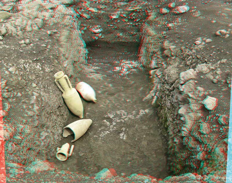
On the first line, original RGB image on the left and converted into CMJN “Euroscale coated” image on the right. The latter is terrible, conversion completely sabred the amphora (the Gallic ones also sabred them to drink them ;-) we are more sober and we satisfy as of printing them).
In lower part, the red, green and blue layers of the two corresponding ones.
On the amphoras, one perceives particularly well the information of the left image eye into the right image eye on the green layer (click to increase). Conversion CMJN brings a color which as well any more does not separate left eye/right eye, the left image is injected into the right image, it is not good.
Notice that this image is assembled without stereoscopic “fault”, it is well with the window.

Bring out layer by layer of the injection of the left channel in the right channel and vice versa
during conversion in CMJN (at the end of the blacks lines add by the author).
The modification +luminous/-contrast does not bring large thing if not only to break contrast and to display it more fade. It always crosstalk due by conversion. The desaturation does not work either. Routing is complicated and is likely to take time for finally losing it. The adopted solution is then to modify the stereoscopic assembly so as to not have a big shift on the amphoras (since are the only really problematic colours on this image) :
Solution 1 : one advances the scene towards the observer and one carries out the stereoscopic coherence cutting.
Another solution if the graphic designer can't stand the stereoscopic coherence cutting (red and cyan area on the left and the right hand side) is deliberately to leave the window violation which is not terrible in this case :
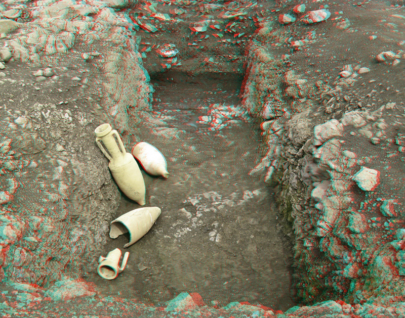
Solution 2 : one advances the scene towards the observer and one leaves deliberately the window violation,
if the computer graphics expert prepress can't cuttings.
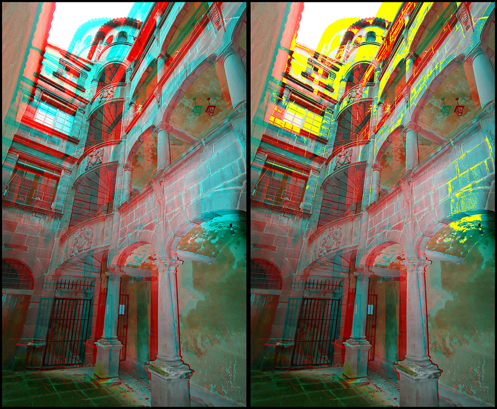
- CMJN version becomes “acceptable” by a color change :
Illustration below original RGB image on the left and the converted image in CMJN “Euroscale coated” on right. The latter is terrible on the top, on the sky (white) and frames it under the grey roof, the staircase. CMJN conversion breaks really right/left channels separation on this level versus originals colors.
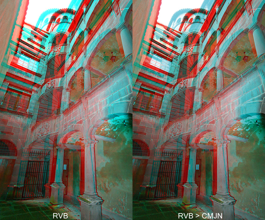
The gamut conversion and synthesis causes an inadequate colors for an anaglyph.
For example, you can see the catastrophe on the green channel (channel right image) where you see the ghost of the left eye channel (red) in the very luminous white sky. The brain wonders well where to locate it because it perceives it at the same time in the two eyes at two different places :
The green layer where the ghost (of the left sight eye) creates by CMJN conversion are obvious.
What to make ? All the attempts luminosity/contrast, dyed/saturation, color temperature are a bitter failure ! The only solution that I could find on this example (cyan channel of a dark object on very white sky) is to modify the color of the white sky by a color of sky which will not cause (or little) of crosstalk during conversion into CMJN. For example, to use a color of sunset with pitch red in the blue sky. Here the result of the retouching by speed routing the sky in the Red and Green+Blue layers in the initial RGB image :
Now, the gamut conversion and synthesis does not cause an inadequate color for an anaglyph.
And if one analyzes the green layer as for the first example with the quite white sky, the ghost of the left channel does not appear any more (or very weak) during conversion into CMJN. On the other hand on the blue layer one perceives it but more luminous :
Magic! CMJN conversion does not cause a ghost of the left channel eye with this sky color.
Let us analyze the differences with the illustration below. One highlights that for the initial image conversion is :
- bad in the red;
- bad in the green;
- bad in blue;
on the other hand, CMJN conversion of the retouch image (color of the sky) is :
- correct in the red, in less bad sense than with initial the because ghost are less contrasted ;
- ideal in the green, there is no more the ghost of the left eye channel ;
- passable in blue, the ghost of the roof is less contrasted and not in the same luminous way as with the initial one.
On the other hand, the retouching anaglyph is much better in CMJN than without the rework.
Differences between RGB and CMJN conversion.
- CMJN version becomes “acceptable” by rework of the stereoscopic assembly and the change of a color, with optimization by iteration of conversion:
Below, the original image assembled to the window (of the pointer of the devil at Puy de Sancy French mountain) with a conversion towards Euroscale coated colors on the left. If you put on your glasses, you will see that the latter is very bad. We are always in the cyan ghost of a dark object (rock) on a very luminous area (white sky). One sees the crosstalk brought by CMJN conversion on the green and blue layers where the image of the left eye is seeing as ghost in the right eye.
Conventional: large ghosts introduces into the right eye by conversion RGB towards CMJN.
The only effective solution that I could find is to change the stereoscopic assembly so as to reduce the red-cyan shift, and, to change the color of sky (white RGB (255,255,255)) by a color which will support conversion well towards the CMJN without bringing crosstalk, the RGB(214,198,224) i.e. a typical reddish blue sky at the time of a sunset. The result is presented below in CMJN Euroscale. They is much better than front but if the red layers are detailed, green and blue after reconversion towards RGB, one distinguishes from the ghost crosstalk on the red and blue layers. The green layer is perfect, he does not have there more no ghost of the left eye. This color is not thus perfect to carry out this conversion into these places of the image. What to make to try to optimize ?
After replacement of the color sky by an adapted color,
there remains of weak ghosts in the right eye (blue) and the left eye (red).
An idea which comes rather quickly is to use the stamp tool of the retouching software (layer by layer RGB) and to stamp the ghosts directly on RGB layers so as to gum them.
The mathematical calculation of RGB conversion towards CMJN and CMJN towards RGB is quite reversible. I.e. that by correcting the problems on the result of a conversion, one tends towards colors which conversion after conversion do not pose problem because they have a solution in both gamuts (sRGB and CMJN Euroscale). The retouch brings a perfect solution to calculation in these particular areas. One can thus make use of it to optimize the image in CMJN by carrying out iterations : RGB - > CMJN - > RGB : retouching with the stamp tool on the layers - > CMJN - > RGB : last retouch - > CMJN : one stops there because one considers it's good. As the gamut sRVB is wider than Euroscale, we go by conversion iteration towards an image whose colors exist in both gamuts. The return to RGB is simpler for retouching the anaglyph, the left and right channels being more intuitive than in CMJN.
Here the result obtained in CMJN after 3 iterations (stamping on sky and stereoscopic coherence cutting), no ghost between the rocks and the sky on all the layers:
- CMJN version becomes “more acceptable” by modifying the luminous flow of the ghost by routing (to increase its luminosity, to change the contrast and the total luminosity of the image):
We are always in the unfavourable case of a CMJN cyan color ghost. In this example we will concentrate on the left side of the Ludesse menhir, the terrible ghost which appears in the sky. A radical solution is the change of the color of the sky as previously explained. If one does not want to use this technique, one can always try to reduce his effect by minimizing it. I.e. to try to make it become less visible.
Conversion below revealed a strong ghost to the left side of the menhir. There is also the tree at the bottom on the right :
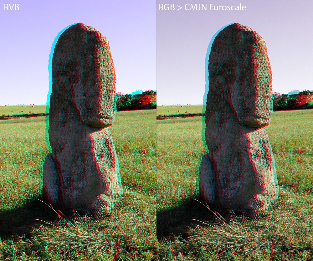
Large anaglyph crosstalk ghost on the left side of the Ludesse menhir and the tree at the bottom on the left, during conversion RGB towards CMJN.
This part which appears for us as a ghost is useful for the stereoscopic vision. It is the shape of the menhir in the image of the right eye. We cannot thus completely remove its limits (for example while gumming with the color of the sky) because the image would become incoherent for the brain. It would miss part of the menhir in an eye which it should however observe in normal situation ! It thus should be routed using the retouch tools of your software, then to act on the characteristics of this color until the tuning which one finds acceptable (but not inevitably perfect).
In the example below, I routed the cyan ghost on the left of the menhir with the magnetic lasso tool (in CMJN image). I increased the ghost luminosity (+ 50%) so as to lower his contrast compared to the sky. In fact, I shifted the initial color of ghost RGB(106,197,224) by a paler color cyan. The ghost became RGB(174,222,242). It less is seen but it is then more difficult to locate the left edge of the megalith :
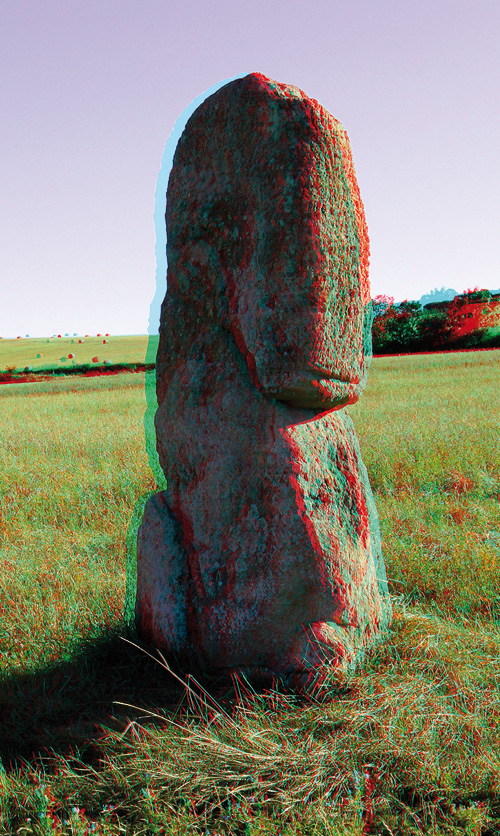
Solution: routing the ghost on the left side of the menhir with the magnetic lasso,
to increase the luminosity in this selected part of the image via the luminosity/contrast tool.
And finally, if one wants to go quickly one can always act on the total tuning of the image with the luminosity/contrast tool. Below, a version with +50% of total luminosity and -100% of contrast to flatten it. The ghost became RGB(154,212,232):
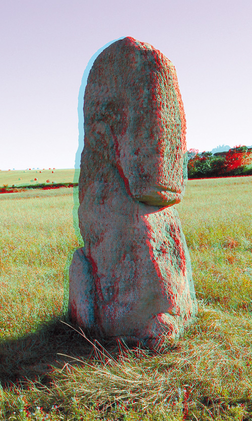
Solution: total processing,
+ 50% of luminosity, -100% of contrast.
These two solutions are not perfectly satisfactory.
Preparation of the anaglyphs to the printing on digital printer or large format printer
I obtained excellent results of printing on personal photographs printers and large digital poster printer (like Canon imagePROGRAF iPF9100). To tell the truth, the manufacturers optimized the fidelity of the colors by the multiplication of primary inks. Thus a offset printing is carried out starting from 4 primary inks (cyan, magenta, yellow and black). Offset printing have the advantage of the speed of printing. It is difficult to multiply inks because the machines would become very bulky and very expensive.
“The small” printers specialized in RGB file printing have now 12 primary inks, 3 times more than offset printing. With these 12 primary inks, the gamut of color reproduction is much wider and offers much more possibility to the subtractive synthesis. The result of the impression is very faithful, quasi comparable with RGB file on monitor screen if the print chain is well gauged. There are few residual ghosts. One will be able to optimize them at the same manner as the methods described for the offset but by using conversion by ICC profile of the specific hardware.
Conclusion
The anaglyphs printing on paper can not function. Indeed, it is necessary to obtain the same separation of the homologous images after conversion into subtractive synthesis starting from an image coded in additive synthesis. The reproducible gamuts between the two systems are not identical and the calculation of this transformation causes colors not adapted to the anaglyphic process. With a retouching software, one can improve this conversion.
The solutions put forward in this Web page result from my experiment. They are undoubtedly not exhaustive. With you to supplement…
Links towards websites :
Complementary documents :